- marketing@technosalesindya.com
- +91-9225322793
Rotary Table Air Chuck
Rotary Table Air Chuck


Mechanical Parameters in mm
| Main Body | Model | ||||||||
| H | G | F | E P.C.D. | d thru hole | D Pilot | C | B | A | |
| M5 x 16 | M5 x 60 | 120 | 70 | 12 | 60 | 2 | 55.1 | 83 | 83-3-2.5 RT TH-12 |
| M5 x 16 | M5 x 65 | 132 | 88.9 | 12 | 82.55 | 2.2 | 60 | 100 | 100-3-2.5 RT TH-12 |
| M5 x 16 | M5 x 65 | 157 | 114.3 | 20 | 101.6 | 2.2 | 60 | 125 | 125-3-2.5 RT TH-20 |
| M5 x 16 | M6 x 65 | 185 | 135.75 | 28 | 125 | 2.2 | 63 | 150 | 150-3-2.5 RT TH-28 |
| 3/8" x 1"- UNF | M10 x 90 | 250 | 183 | 50 | 167.6 | 7 | 90 | 203.2 | 200-3-3 RT TH-50 |
Technical Parameters
| Max. R.P.M. (r / min) | Jaws | Model | ||
| Total Gripping Force (kNf) - 6 Bar * | Stroke On Diameter (mm) | No. Of Jaws | ||
| 100 | 4 | 2.5 | 2,3 | 83-3-2.5 RT TH-12 |
| 90 | 7.5 | 2.5 | 2,3 | 100-3-2.5 RT TH-12 |
| 70 | 12 | 2.5 | 2,3 | 125-3-2.5 RT TH-20 |
| 60 | 20 | 2.5 | 2,3 | 150-3-2.5 RT TH-28 |
| 45 | 38 | 3 | 2,3 | 200-3-3 RT TH-50 |
* Total Gripping Force is calculated without top jaws.

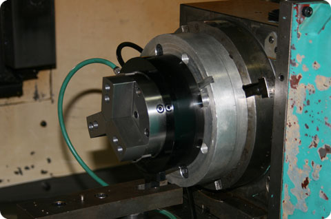
Rotary Table Precision Air Chuck mounted on 4th axis

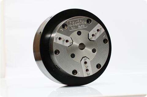
Model: 100-3-2.5 RT TH-12
This is Ø100MM rotary table precision air chuck, 3 jaws, 2.5MM stroke, 12MM thru hole.
This is Ø100MM rotary table precision air chuck, 3 jaws, 2.5MM stroke, 12MM thru hole.


